With this article we explain the dBricks data model in a simplified form and we highlight the reasons why we realized it in this way.
For better understanding we use system examples from the field of aerospace. But please recognize that dBricks can be used for any system development of any technical sector.
Our goal is to optimize the:
The must-have prerequisite for success is the consistent and explicit definition of all interfaces between the system devices.
To implement a system means to fulfill a bunch of considerations and decisions. All of them must be done consistently and every design aspect affects other system properties. Having a consistent method to avoid iterations saves a lot of effort.
The following steps show how you can act according to best practice.
Any system is composed of actors that exchange data. In case of an aircraft subsystem these actors are so called devices. These devices:
For example:
The pilot needs the information of the actual pitch angle to control the airplane. This angle must be displayed on the so-called Display Unit (DU) inside the cockpit. The DU is not able to measure the pitch angle itself and therefore needs to receive this information. The Air Data and Inertial Reference Unit (ADIRU) measures the pitch angle of the aircraft and can provide this information to the pilot's DU.
Both device interfaces need to support the exchange of the parameter for pitch:
In order to interpret this parameter in the same way it is necessary to define parameter properties as well. Obviously both actors must interpret the parameter, in the same way, to use it correctly. In many development projects implicit data type conversions are the source of an enormous number of development problems!
For our pitch information we define the following properties and assignments:
In our system example we additionally define the Flight Control Computer (FCC) which also subscribes the pitch information to function properly.
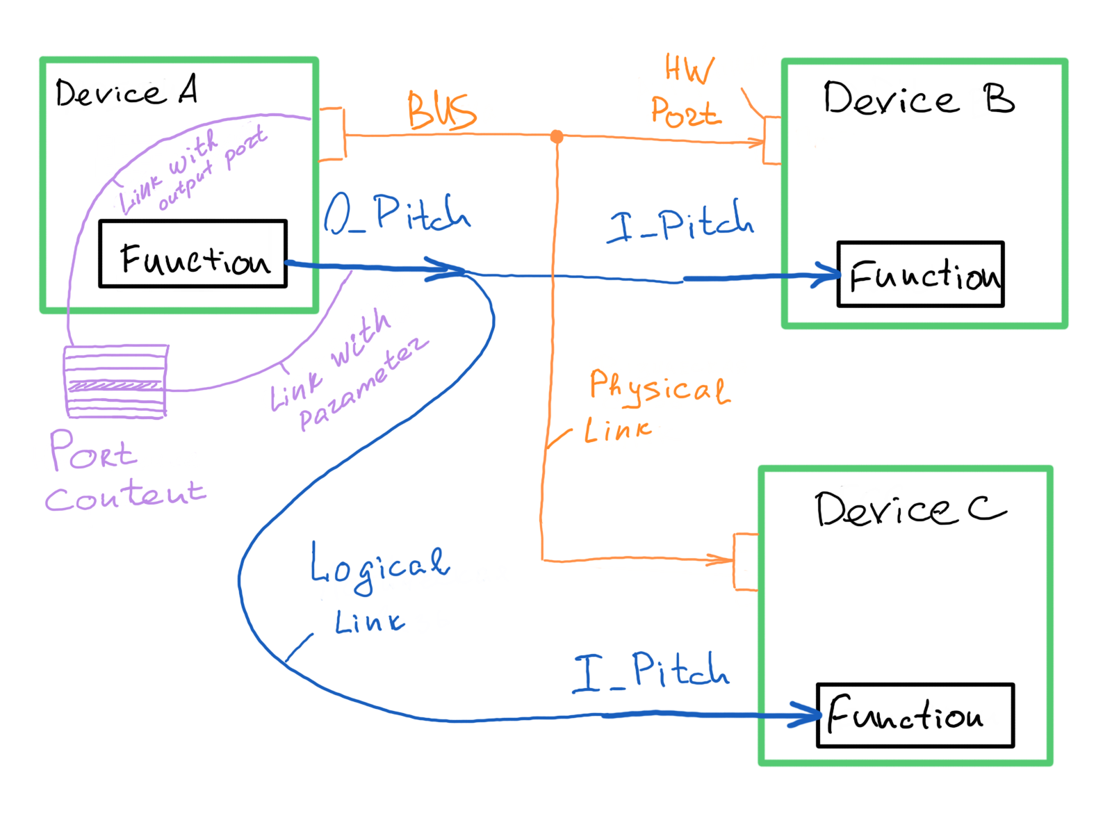
Combined the system interface diagram looks like this:
While proceeding with the interface definition natural needs are coming up:
One of the dBricks major features is the split between device definition and project definition. The device template describes the device as it would be off-the-shelf - independent of the project where it is used in. If you need to make changes in every device in any project it will be enough to update the device template only once.
Our example project uses numerous hardware devices of the same type: two ADIRUs.
In order for being able to use them in a normalized form we follow these steps:
The arrows in the picture show the relation between device templates and the devices in the project. Using the templates means that no new identity has been created. Every device is described only ONCE at ONE place.
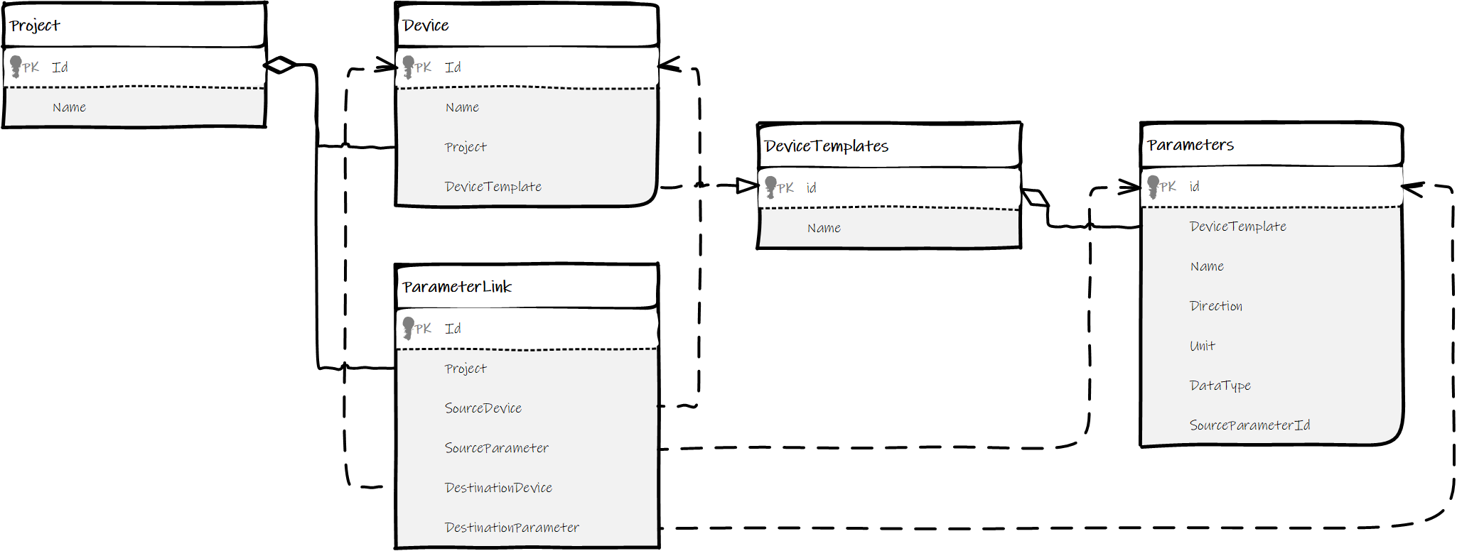
Every project is an interface data model which is not a single entity. It is an object consisting of other objects which are linked with each other.
In the preliminary steps we have defined the data to be exchanged in our system. To complete the system definition we still need to describe:
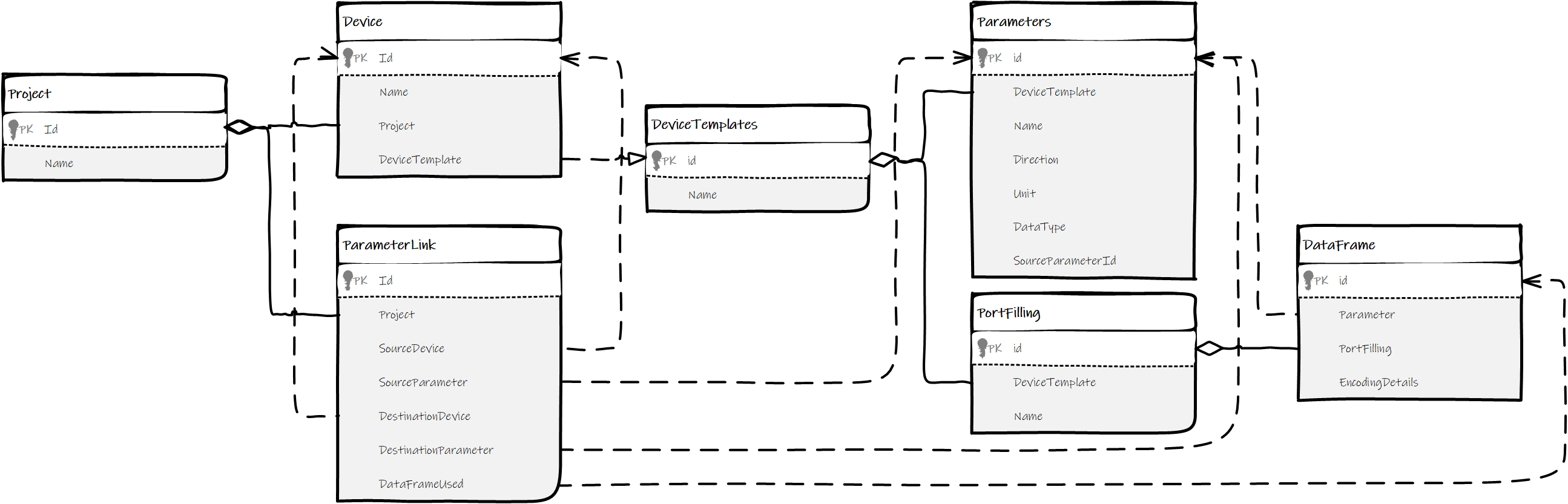
In order to do the physical interconnection the data model needs to hold additional entities:
Exchanging a parameter sounds simple. Nevertheless, there are many possibilities how this parameter can be transferred and how submitter and subscriber interpret it. In order to assure correct "understanding" on both sides it is important to define:
For the description of all necessary encoding/decoding details, we introduced an entity we call "port filling". It contains all specification information of how parameters are encoded/decoded and serve as a bridge between logical data transfer definition and physical connection. This entity is a part of the template description and therefore available for any instance generated from this template. Port filling objects can be assigned to one or several outputs or duplex hardware ports. This saves a lot of maintenance effort as it is usual that devices contain numerous similar output ports.
The port filling is protocol-specific, but it always contains a list of parameters to be transferred and explicit coding details.
See this example using the ARINC429 transport layer:
As you might know, A429 data exchange is composed of 32-bit words. These words are normally transferred on a regular basis with a predefined refresh rate that has to be defined. To distinguish one word from another the 8 start bits of each word contain labels. And finally, most of the parameters in A429 transfer are coded in fixed-point data format so we need to define the least significant bit, most significant bit value, and size.
At this point we finalized:
The created structure provides us easy validation. We can assure consistency by checking that all defined parameter links contain the relevant encoding details and are supported by wiring design. This consistent structure is the perfect base for automatic checks and dBricks scores by performing these automatic checks.
Of course engineering in real-life brings up a lot of tricky features and exclusions. But what is an engineer without challenge? ;-)
The general idea stays always the same despite all exclusions:
Finally to stick up with dBricks:
Once you have achieved the interface data model dBricks will help you with lots of additional features to make your daily work easier. It provides data reports including formal documents like schematics or even a complete interface control document (ICD). It provides you non formal analytic reports that help you to design the best possible system.
Just check it yourself: Get Demo Access
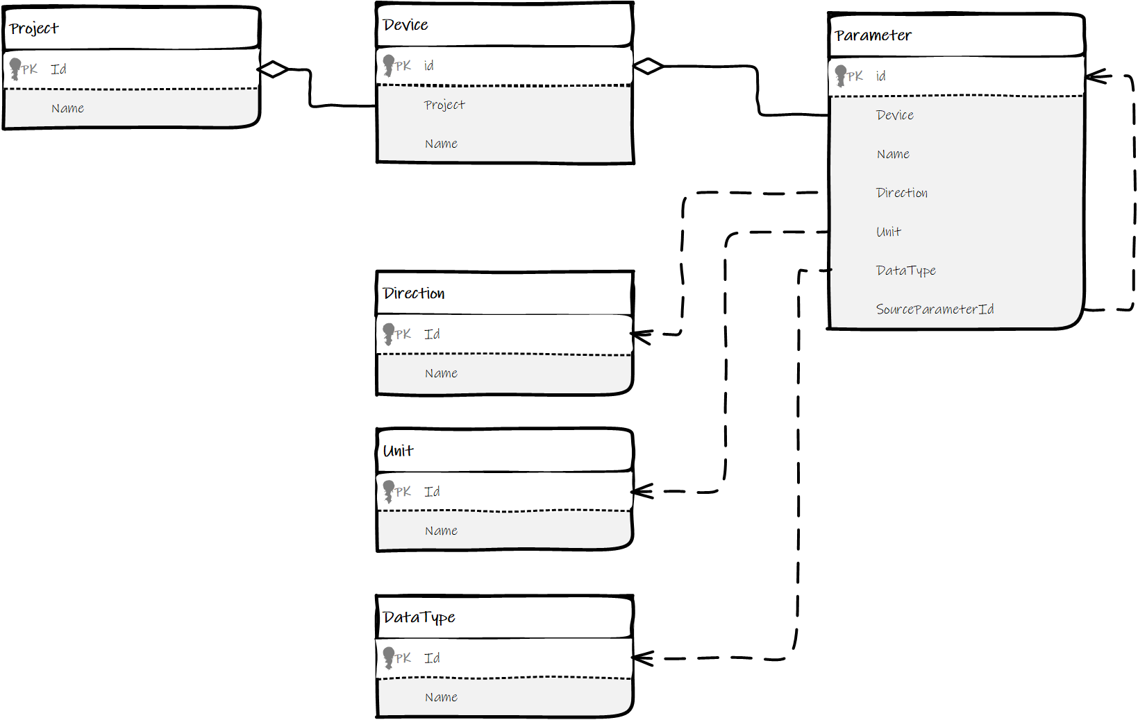
P.S. Hereuder you can find some simplified data model diagrams related to each abovementioned step.
UML Diagram for step 1
UML Diagram for step 2 UML Diagram for step 3
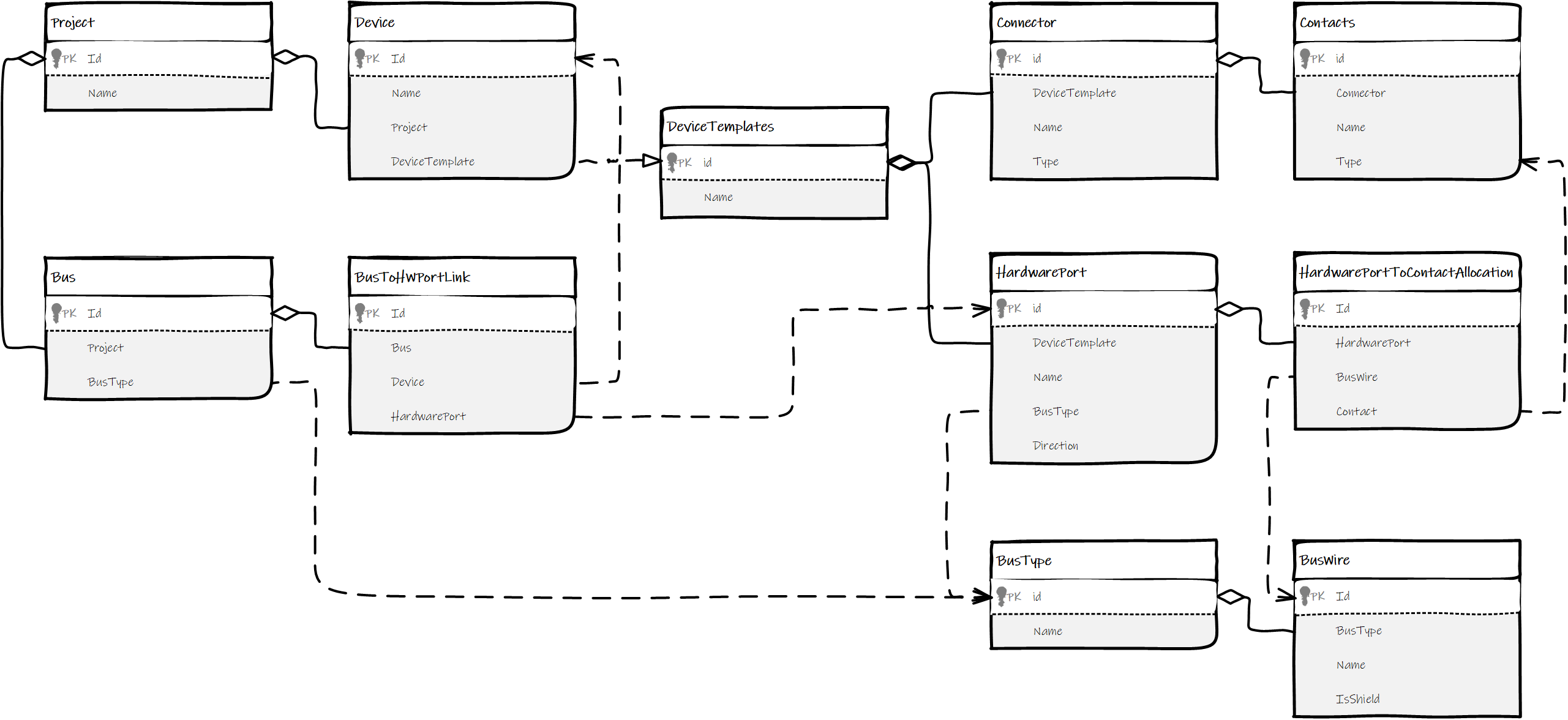
UML Diagram for step 4